There’s been quite a demand for black telephones of late. I’m not sure quite why, but I’ve got to go with the flow and repair and polish up some more.
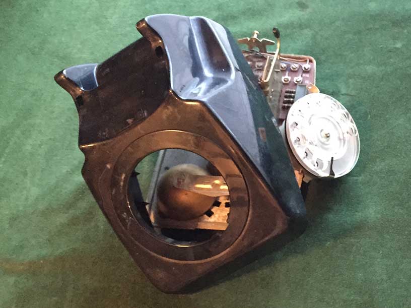
Above – The usual condition they turn up in. After a full clean, polish and replacement of the broken parts, such as leads, dial mechanism parts, and then fitting a concussion diode and a REN dropper resistor, all is well again.
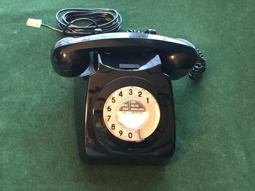
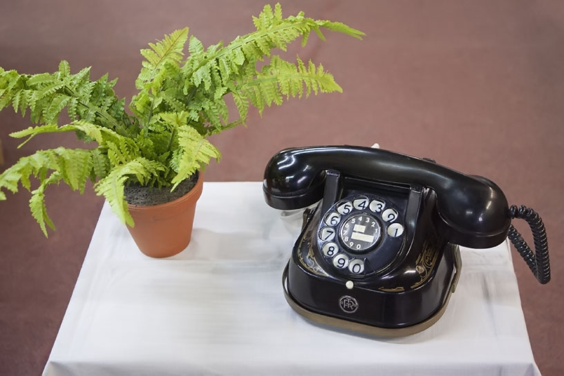
Above – Final touches like fitting a newer type microphone for better speech and a centre number card finish off the refurbishment.
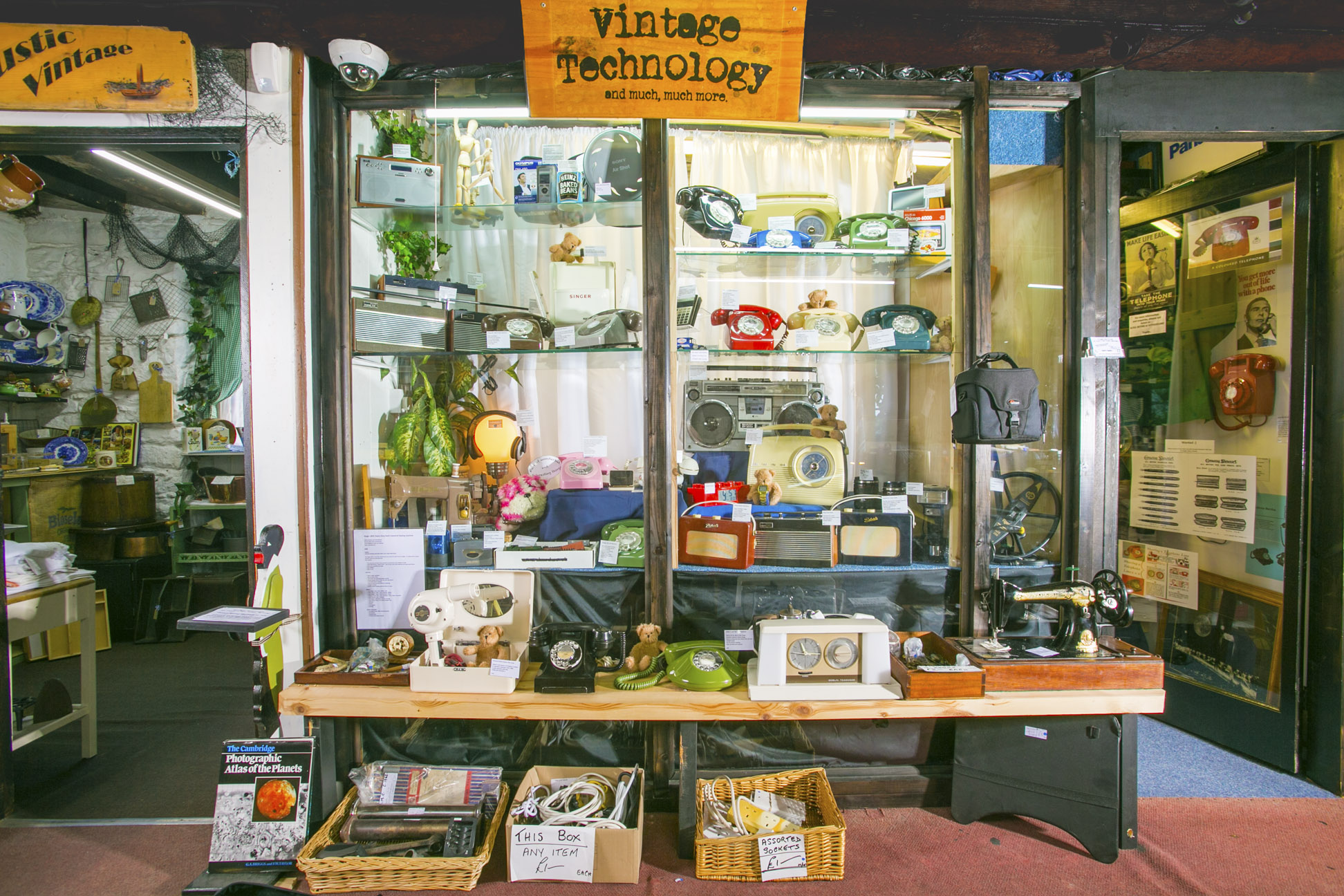
We have lots of lovely telephones in stock, including trimphones and novelty telephones, so just give us a call, to see if we have what you need.