
Apologies, as this is a really long post. However if you want or have one of these units it might actually save you a lot of hard work.

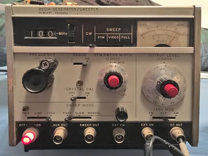
I got this quite some time ago, and it was about time to repair it ready for use.
So, first things first, the original mains lead had snapped at the plug end internally and the wires have turned hard, so it won’t be long before they break or short out internally causing all sorts of unpleasantness. I decided to upgrade the socket to a somewhat more modern design Looking at the service diagram the old socket has filter coils and capacitors moulded into it.Digging about in the spares box I found an old filter capacitor set from a computer power supply unit which had the same specifications as the old old one. I grafted this on to the socket and connected all of the outputs to their respective places, the only thing to do now was to very carefully remove a section of metal and file it down so it looked neat and tidy.
Knowing that the unit powered up to some extent I tested the output for a signal, nothing. Luckily on this model it only has three hybrid ic’s and you can swap them around for each other temporarily for fault finding purposes. On doing so I got a strong signal but was unable to alter frequency. All of this meant one of the output preamplifier hybrids was faulty. So all got put back to their original places and I powered up the oscilloscope. The top preamplifier had lots of signal in but not much out.
If it was the final power amp I would have probably just bought one of this gentleman’s fine replacement examples, but this was the preamplifier, so I decided to take the lid off carefully and have a look inside to see if there was anything obvious. Under the microscope you could just see that the transistors were looking a little sad for themselves, which was confirmed by very carefully testing with a meter confirming that the emitters were almost open circuit. The plan was to solder compatible transistors onto the hybrid directly with fine wires for base and emitters to the appropriate places. Borrowing from his research the BFE35 transistors seemed a pretty good match for what was needed, so I ordered a few to experiment with.
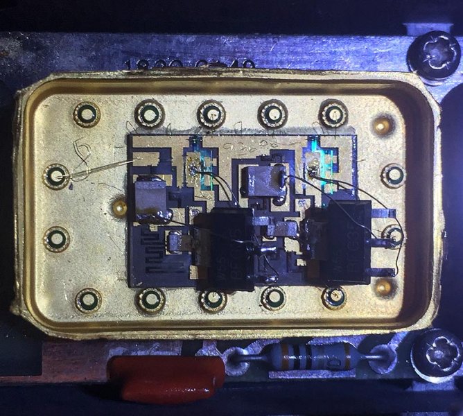
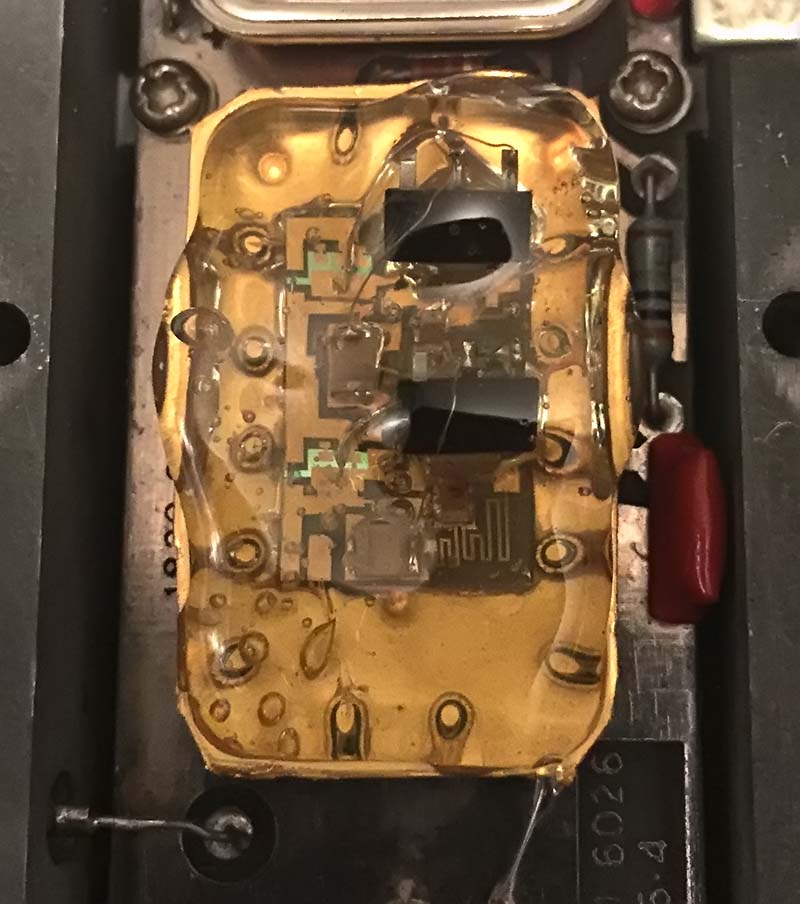
Using a fine pair of tweezers and a micro tip soldering iron I soldered on the new parts very carefully, so as not to damage anything else and powered up. Instant signal

After grinning like a muppet for a while I discovered I was not completely done yet. Whilst it worked perfectly on the lower frequency scale, it had no signal on the upper scale. So, to rule out any spurious problems with switches I spent the next hour cleaning up all of the contacts on all of the switches and getting all of the dust out. Now it was much nicer to use, but the upper scale still didn’t work. Grabbing the service manual and printing out the various flow charts and diagrams, it was obvious HP don’t like engineers very much. The manual is a bit of a mess, and bits of it was scattered throughout the entire manual with no logic behind anything. However after working out how they wanted you to service the item things began to fall into place. First port of call was the divider assembly, there is a perfectly good signal on the 0-11 scale, but from the 11 to 110 MHz range there was absolutely nothing. After carefully removing the divider board and checking the signals on the chips something didn’t add up. One of the chips had a random signal on its output, and even then it was barely there.
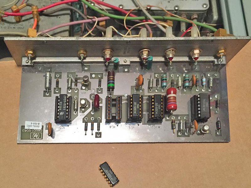
Naturally on checking, none of these chips are available any more, partly because they’re HP branded versions of Motorola’s chips, and also the fact that Motorola don’t make them any more anyway. Thankfully some kind soul had put an equivalent table for the chips online which led me to find an equivalent to the faulty one which was numbered 1820–0102 and its replacement is an MC1013p. I managed to find someone selling some ‘new old stock’ of these online and quickly ordered up a few.
Now is the new chip installed and fitted the upper frequency was now reinstated. Another small dance ensued
that was, until I tried to use the sweep function, The signal went dead. I was beginning to believe that this was made up of an entire bunch of these units that were all faulty and I,d ended up with all the broken bits from halfway around the planet. When the sweeper was switched from carrier wave to sweep the signal would die. Not quite sure where I was to actually go next I decided to work through the alignment procedure on each one of the packs to see if anything was grossly out of alignment. First couple of packs seemed to be okay, those being the power supply, and the crystal oscillator adjustments, I gave him a bit of a tweak whilst I was there to get them spot on. Next up was the voltage tuned oscillator, the first thing I noticed was when you disconnected the lead to do the initial adjustment, the signal went dead. So I removed this board and went around testing voltages around the various areas. Something didn’t seem right, there was 75V on everything and whatever frequencies were there, were all over the place. so obviously something was wrong here to, on closer inspection like with all the other boards this one didn’t seem to match anything to do with the serial number, so was yet another of somebody’s broken lineup of products.
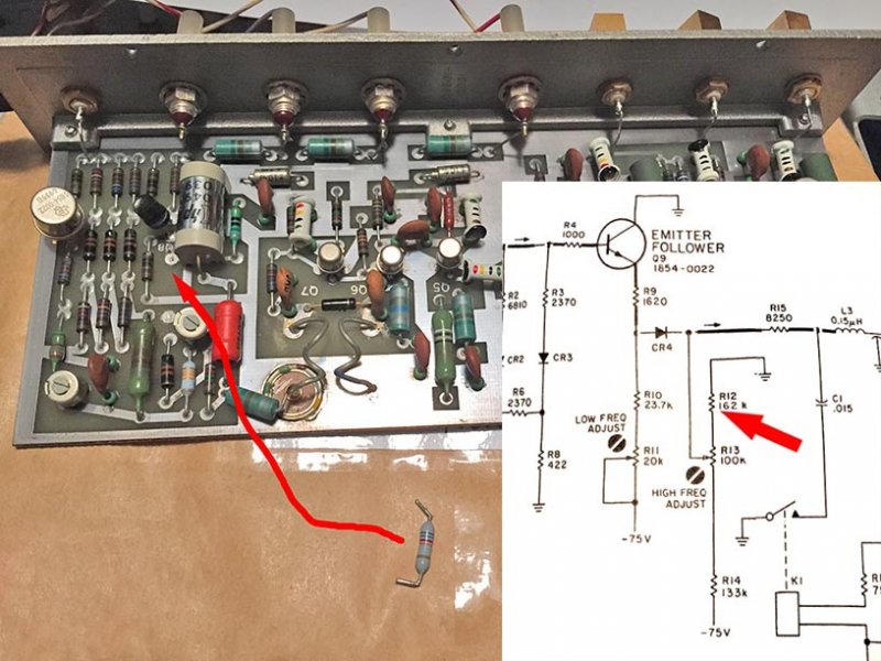
After a little while I managed to find a open resistor (shown above) and on the replacement of this and a quick set up of the now very grossly out of adjustment oscillator, I finally had a working piece of test equipment on every single setting.
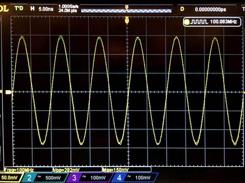
Phew, this all took just about a week to achieve between various other jobs that came in needing to be done, But at least now I have a very nice piece of test equipment that I can use to set up the IF stages of radios. You can actually just sit a radio on top of the unit and it gives off a enough RF to hear the broadcast tuning past the radio’s tuned point. If you see what I mean.
So that’s it, I will probably refurbish the cabinet of this unit at some point, but for the meantime I’m just going to enjoy using it.
All the best out there in radio land, Ast.